Structure and working principle:
Working principle
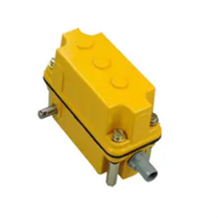
The displacement signal of the DXZ type stroke limiter and the controlled mechanism is connected to the input shaft of the limiter after the external change gear is changed, and the angular displacement signal of the output shaft is converted into the angular displacement signal of the output shaft by the speed reducer.
Product description:
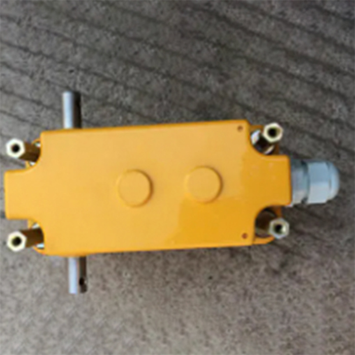
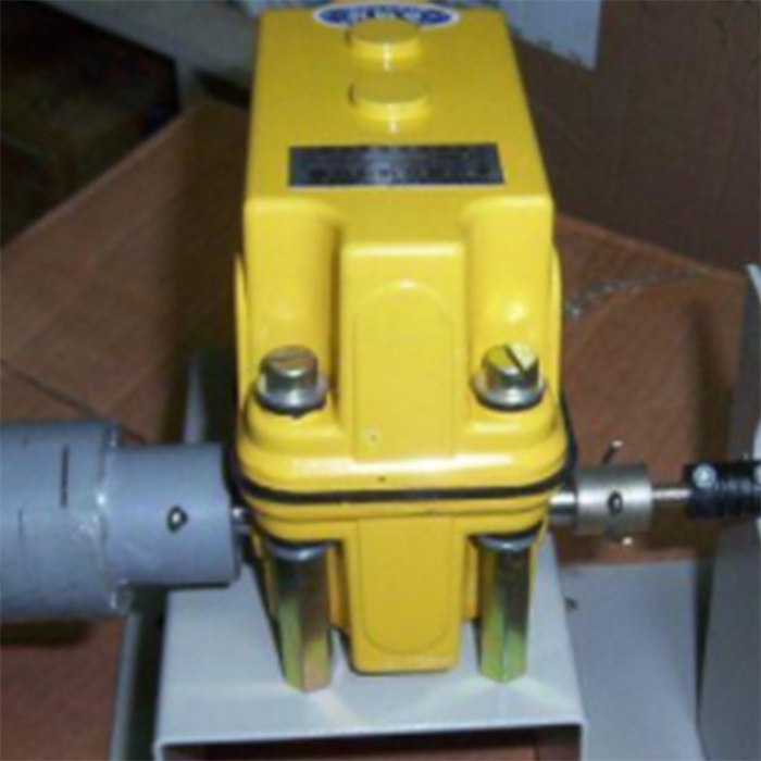
(limit switch) is suitable for AC 50Hz. In a control circuit with a voltage of 380V and a DC voltage of 220V, it is used to control the stroke of the movement mechanism or to change its movement direction or speed. It can be widely used in the control and limit of the spatial three-coordinate of the lifting and transmission machinery in the construction, port, mining and other industries. It has small size, multi-function, high-speed, adjustable limit, strong versatility, maintenance, installation, and use adjustment Convenience and other features.
Product parameter:
1.Ambient temperature: 233-328K (-40–+55℃)
2.Relative humidity: not more than 90
3.Transmission ratio: 1:13—–1:960
4.Repeated positioning degree: the angle error of the memory cam is not more than 0.005rad
5.Rated voltage: AC: 125—250V DC: 30V
6.Rated current of the device: 6A
7.The control loop design loop is 1-4, and 5-6 control loops can be added according to user needs.
Installation and adjustment
The memory cam and micro switch corresponding to the adjustment axis of the DXZ type stroke limiter are:
1Z—1T—1WK; 2Z—2T—2WK; 3Z—3T—3WK; 4Z—4T—4WK;
DXZ type stroke limiter adjustment program:
1.Disassemble the upper cover, check and tighten the 2-M3×55 screws.
2.Loosen the M5 nut.
3.According to the need, set the controlled mechanism to the open position (no load). At this time, the micro switch corresponding to the control of the mechanism should be switched instantaneously.
Namely: adjust the corresponding adjustment axis (Z) so that the memory cam (T) presses down the micro switch (WK) contact.
1.Tighten the M5 nut. (The nut must be tightened, otherwise memory disorder will occur).
2.The organization should run repeatedly without load several times to verify whether the memory position is accurate. (Repeat the above adjustment if there is an error).
3.Confirm that the position meets the requirements; tighten the M5 nut and install the cover.
4.After the organization works normally, check whether the memory control position has changed frequently, so as to make timely corrections.ProductPhotos:

 English


